 Skip to content
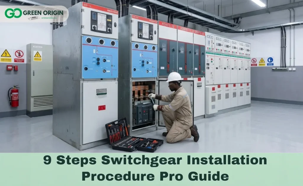
The switchgear installation procedure determines the long-term safety, reliability, and compliance of every power distribution system, According to IEEE Standard 493, improper installation is a leading contributor to electrical equipment failure, resulting in significant network downtime as well as serious financial and safety consequences.
Understanding the full switchgear installation procedure—from site preparation through commissioning-is essential for any engineer or project manager responsible for MV or LV power distribution projects.
What Is the Switchgear Installation Procedure?
The switchgear installation procedure is the complete sequence of preparatory, mechanical, electrical, and commissioning steps required to bring switchgear safely into service, A proper electrical switchgear installation begins before the equipment arrives on site and ends only after all protection and control functions have been verified under energized conditions.
Who performs switchgear installation?
Switchgear installation must be performed by qualified electrical personnel with:
- Formal training in HV/MV electrical safety per IEC 62271-1 and local regulations.
- Competency in protection relay testing and circuit breaker racking procedures.
- Authorization to work on energized or recently de-energized equipment.
- Two-person operation rule – one operator, one safety observer at minimum.
Read More: What Is Switchgear and Its Types for Industrial Projects?
Key Safety Standards and IEC Guidelines for Switchgear Installation:
Every switchgear installation procedure must comply with applicable international standards, The primary governing standards are:
- IEC 62271-1: Common specifications for HV switchgear and controlgear – covers service conditions, rated characteristics, and design requirements, See: IEC 62271-1.
- IEC 61439-1 & -2: General rules and power switchgear assembly standards for LV switchgear – defines responsibility for compliance and type-testing, See: IEC 61439-1.
- IEEE C37.20.2: Standard for metal-clad switchgear – covers construction, testing, and installation requirements for MV metal-clad assemblies, See: IEEE C37.20.2.
- NFPA 70E / IEC 60364-7-729: Minimum working space and aisle clearance requirements – corridor width and door-swing clearances mandatory for safe maintenance access, See: NFPA 70E.
Read More: Difference Between Switchgear and Distribution Board.

Step by Step Switchgear Installation Process:
The following step-by-step switchgear installation procedure applies to indoor MV and LV metal-enclosed assemblies, When installing switchgear outdoors or in seismic zones, additional site-specific requirements apply:
- Site preparation: Level concrete pad ≤ 1.6 mm/yd² tolerance; stub conduits max 25 mm above floor; 2.1 m clear aisle in front.
- Receiving and inspection: Verify rated parameters against drawings; check transit damage; confirm voltage, short-circuit breaking current, and IP rating.
- Positioning and alignment: Chalk line or laser baseline; bolt shipping sections together; release shipping braces before load.
- Busbar installation: Phase sequence A-B-C; torque M12 bolts per Mfr. Torque Chart; megohmmeter test ≥1000 MΩ or per manufacturer.
- Grounding: Independent earth for enclosure, core, and neutral per IEC 60364; verify continuity before energization.
- Cable termination: Terminate per manufacturer spec; verify phase ID; heat-shrink stress cones for MV cables.
- Control wiring: Follow color-coded diagrams; verify protection relay connections and trip coil circuits.
- Pre-energization testing: Insulation resistance; contact resistance; relay secondary injection; interlock verification.
- Energization: Power supply side first; verify phase rotation; confirm indications and metering before applying load.
Read More: High Voltage Cable Testing Methods: IEC Standards & Procedures.
Switchgear Installation Failure Statistics and Common Mistakes:
Per IEEE Standard 493, moisture exposure contributes to 30% of switchgear bus failures – and partial discharge accounts for nearly 26% of insulation failures in electrical switchgear installation:
- Incorrect busbar torque: Under-torqued connections cause overheating – use a torque wrench with data logging and save the tightening record.
- Insufficient clearances: Failure to maintain aisle widths per IEC 60364-7-729 blocks emergency egress and safe breaker racking.
- Moisture ingress during storage: Equipment stored without environmental controls suffers insulation degradation before first energization.
- Skipping pre-energization tests: Insulation resistance and contact resistance testing are mandatory before any MV or HV switchgear is energized.
- Wrong phase sequence: A-B-C must be verified before load connection – reversed rotation damages motors and causes mis-coordination.
Every step of the switchgear installation procedure must be documented – a signed checklist is required for warranty validity and insurance compliance.
Read More: What Is Arc Flash Resistant Switchgear and Its Types?
Switchgear Installation Checklist Before Energization:
A complete switchgear installation checklist must be signed off before any switchgear installation procedure proceeds to energization:
| Checklist Item | Status | Standard |
| Concrete pad level within 1.6 mm/yd² tolerance | Pass / Fail | Mfr. spec |
| All shipping braces removed | Pass / Fail | Mfr. spec |
| Busbar torque record completed | Pass / Fail | Per Mfr. Torque Chart |
| Busbar insulation resistance (≥1000 MΩ or per manufacturer) | Pass / Fail | IEC 62271-1 |
| Earth continuity verified | Pass / Fail | IEC 60364 |
| Cable terminations inspected and labeled | Pass / Fail | Mfr. spec |
| Protection relay secondary injection complete | Pass / Fail | IEEE C37.20.2 |
| Mechanical interlocks tested | Pass / Fail | IEC 62271-1 |
| Minimum aisle clearances confirmed | Pass / Fail | IEC 60364-7-729 |
| All tools and personnel clear of enclosure | Pass / Fail | NFPA 70E |
Read More: Switchgear Components List and Specs for Projects.
Why Green Origin Is Your Trusted Partner for Switchgear Projects?
Green Origin supplies MV and LV switchgear pre-tested and pre-configured to simplify every switchgear installation procedure on site, Every unit arrives with a complete switchgear installation checklist and factory acceptance test (FAT) report – so teams spend less time installing switchgear from scratch and more time on site verification.
Every Green Origin switchgear project is supported by:
- IEC 62271 and IEEE C37 certified assemblies: Full type-test documentation for project approval and utility tender submissions.
- Factory Acceptance Testing (FAT): All protection, control, and interlock functions tested before dispatch – reducing site commissioning time.
- Technical installation support: Green Origin engineers available for site supervision, commissioning assistance, and protection coordination studies.
- Comprehensive spare parts supply: Fuse links, relay modules, and contact assemblies available for fast replacement – minimizing downtime after any fault event.
Read More: Top Switchgear Companies in World.
Explore Switchgear Systems and Electrical Solutions by Green Origin:
Green Origin provides complete switchgear installation tools and assemblies for every voltage class:
- MV Metal-Clad Switchgear (11–36 kV): IEC 62271-200 certified; vacuum circuit breakers with motorized closed-door racking – reducing arc flash exposure during installation and maintenance.
- LV Switchgear Panels: IEC 61439-2 certified; MCCBs, ACBs, and motor control centers for secondary distribution.
- Ring Main Units (RMUs): Compact SF6 or vacuum insulated – pre-wired and factory tested for fast site installation.
- Commissioning and testing kits: Complete switchgear installation tools including torque wrenches, megohmmeters, and secondary injection test sets.
Ensure a flawless switchgear installation procedure with Green Origin’s pre-tested and IEC-certified assemblies. For expert site support, inquiries, or OEM requests, reach out directly via Contact Us or WhatsApp, email our engineering team at contact@greenorigin-elec.com, or explore our complete product range on the Green Origin website.
FAQs:
Does switchgear need to be installed on a raised concrete pad?
Yes – level within 1.6 mm/yd², finished flush with aisle surfaces to enable circuit breaker lift truck access and prevent enclosure distortion.
What is the minimum required clearance around electrical switchgear?
Per IEC 60364-7-729, typically 1,000 mm for single-door access and 1,200 mm when two door leaves face each other.
What are the recommended torque specifications for switchgear busbar connections?
M12 bolts torqued per manufacturer’s torque chart using a calibrated torque wrench – tightening record retained as part of installation documentation.
How long does it take to install switchgear?
A single MV section requires 2–5 days, Complex multi-section lineups with protection systems require 2–4 weeks.
